CHRYSLER CROSSFIRE ME2.8 IMMOBILIZER EMULATOR
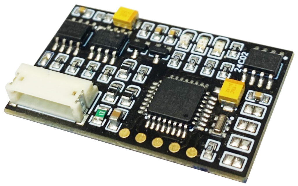
This emulator replaces the immobiliser SKREEM communication signal on the CAN bus to unlock all ME2.8 ECU variants used on Chrysler Crossfire vehicles.
This also applies to converting these engines for buggies, boats, or racing vehicles.
In order to use this emulator, the hash key data must be written to the I2C 24C02 memory of the emulator.
No change is needed to the flash memory or eeprom of the ECU itself, which remains in its original state.
In the process of adding the emulator to this ECU, we have the choice of which key position 0 to 7 we want to use in the emulator, which makes it possible to retain the codes of the original keys.
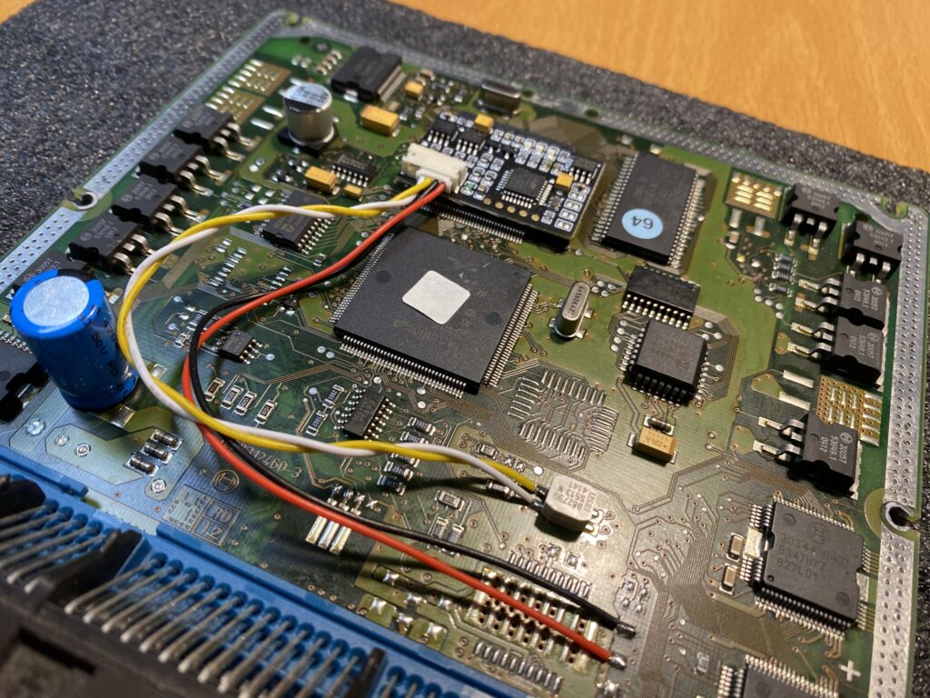
The emulator has the function of automatically reading from the ECU the list of hashes necessary for calculating the emulator key, which makes its installation easier. The read list is saved to the EEPROM I2C 24C02 of the emulator and must be sent to me for the calculation of the key from the correct position.
In order for this procedure to work, the ECU must be in working condition, not virgin, and have undamaged EEPROM content after attempts to perform a renewal.
After calculation, we send back the valid contents of the eeprom to be stored in the emulator memory.
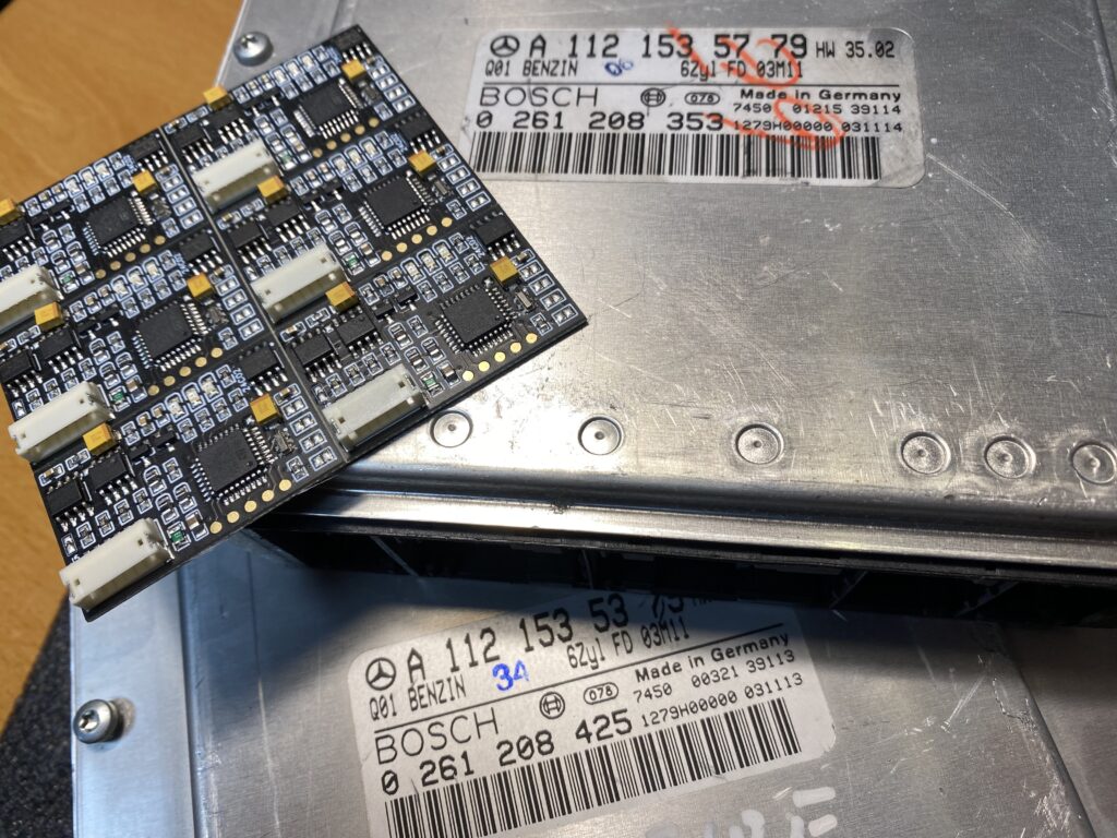
Examples of engine control unit numbers compatible with this emulator : 0261208425, 0261208995, 0261208402, 0261208353, 0261201163, 0261208799 and all others.
It is important that the ECU is from a Chrysler Crossfire and not from an MB, for MB we have a different emulator FBS3 which controls the starter via CAN bus .
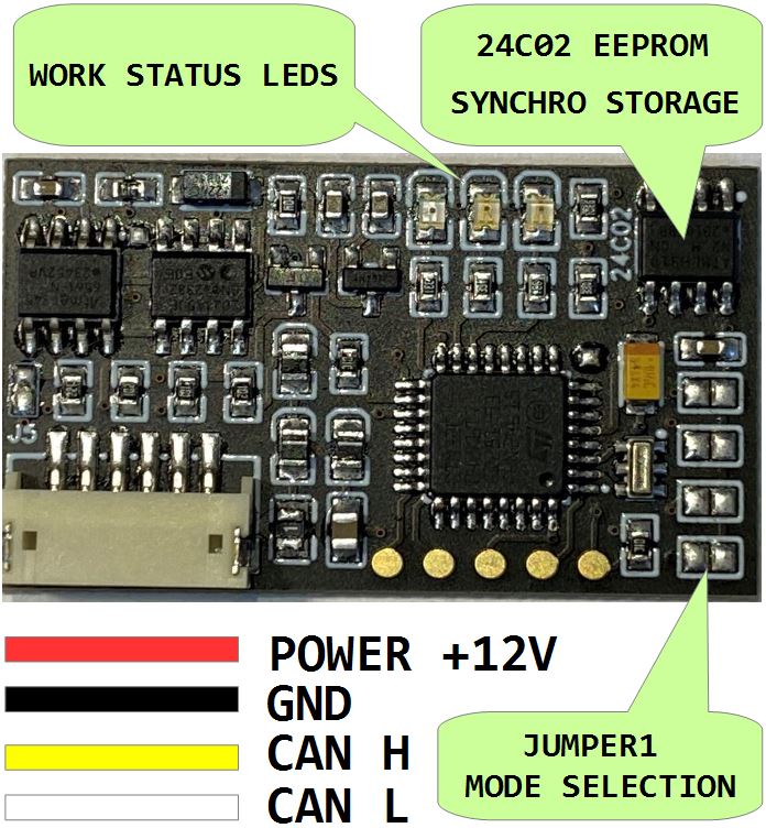
Four wires should be connected: CAN-H, CAN-L, GND (ground) and +12 V IGN ( terminal „15”) or +12 V after the POWER relay.
Ensure the connection adheres to the vehicle’s repair schematics.
The colors of the corresponding wires are specified in the photo.
The location of the eeprom 24C02 memory is also specified in the photo.
Please remember the CAN terminator – terminator resistor J5 jumper, is in many cases indispensable especially when the ME2.8 ECU works standalone.
On emulator PCB we have 3 x LED GREEN, RED, YELLOW, thanks to them we can carry out diagnostics of the emulator connection, they clearly indicate the current status of the CAN bus connection and the status of matching to the ECU.
If you are an EU-based automotive electronics company, you can send us an engine control unit for assembling and testing the emulator for service – please contact us or to one of My distributors .
In order to use this solution, the customer must be qualified as an automotive electronics technician and have the necessary diagnostic tools and wiring diagrams.
In the event of problems and the need for technical support, a CAN bus analyzer will be required in addition to the ECU files, as well as the ability to operate it.
