
PSA FINDER EMULATOR
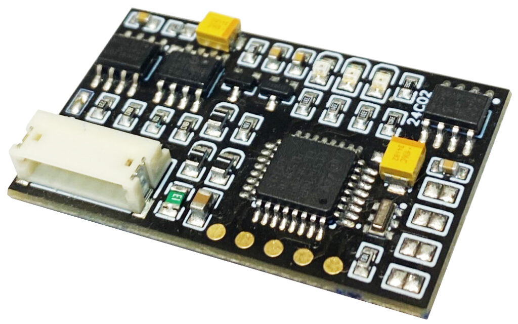
Device for reading the PIN code and immobilizer emulation, designed for
the engine ECUs of PSA group vehicles.
The device reads the security code through a direct connection to the CAN bus of the controller, without the need for opening the ECU.
The main target of the application of PSA FINDER are the latest controllers ECU :
MD1CS003, MG1CS032, MG1CS042, DELPHI DCM6.2A, DELPHI DCM7.1A, VALEO V46.x, VALEO V56.x, VALEO VD46.x, VALEO VD56.x, EDC17C10, EDC17C60, EDC17CP42, CONTINENTAL SID807EVO with implemented the latest software library of the PSA immobiliser system.
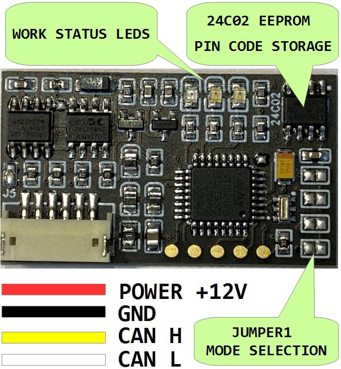
SETTING THE OPERATING MODE IS DONE VIA JUMPER 1 :
- JUMPER OPEN : Pin code scan mode. You can use this mode as many times as you like, there are no restrictions.
- JUMPER CLOSE : Immobilizer emulator mode. You can use this mode as many times as you like, there are no restrictions.
PIN CODE SCAN PROCESS
- CONNECT THE EMULATOR TO THE CONSTANT (30) 12 V SUPPLY. The ECU must be connected to a switchable power supply 15 (IGN).
- WHEN THE EMULATOR IS POWERED ON, the red and yellow LEDs light up simultaneously.
- AFTER SWITCHING ON THE ECU POWER SUPPLY, when the ECU starts the CAN bus communication process, the yellow diode will flash, indicating the entry into Phase One of the scan. The duration of Phase One is impossible to determine, but in practice, it lasts from 15 to 60 minutes (a longer duration is also possible).
- WHEN THE EMULATOR PERFORMS THE FIRST SUCCESSFUL AUTHENTICATION, it enters Phase Two. The yellow diode goes off, and the red diode starts flashing. From this moment, the time to calculate the correct PIN code is up to 15 minutes.
- AFTER THE CALCULATION OF THE PIN CODE, the emulator proceeds to Phase Three of the authorization test.
- UPON SUCCESSFUL VERIFICATION OF THE PIN CODE, the green diode goes on, and the red one blinks only very briefly each time the emulator receives a request from the ECU.
- WHEN THE GREEN LED IS ON, the emulator writes the found PIN code to the EEPROM 24C02 memory mounted on the emulator PCB at address: 0x10. It can be read with any programmer supporting the I2C bus.
IMMOBILIZER EMULATOR MODE:
IN CASE EMULATOR MODE : CLOSE JUMPER 1 MODE SELECTION, DO CONNECT EMULATOR THE IGN (15) 12 VOLT POWER SUPPLY, GROUND AND CANBUS YOU CAN USE THIS MODE AS MANY TIMES AS YOU LIKE, THERE ARE NO RESTRICTIONS.
- ECU AND EMULATOR TOGETHER CONNECTED TO POWER SUPPLY AFTER IGNITION SWITCH (15 IGN) IN THIS MODE, AFTER SWITCHING ON THE POWER BOTH YELLOW AND RED LEDS LIGHT UP.
- WHEN THE ECU SENDS A REQUEST TO THE EMULATOR VIA THE CAN BUS, THE YELLOW AND RED LEDS GO OFF.
- THE EMULATOR CARRIES OUT THE AUTHENTICATION AND ANALYSES THE RESPONSE OF THE ENGINE CONTROL UNIT, IF THE ECU HAS BEEN CORRECTLY UNLOCKED THE GREEN LED LIGHTS UP, OTHERWISE THE RED LED WILL LIGHTS UP.
EXAMPLE VIDEO USAGE PSA FINDER EMULATOR
In order to use this solution, the customer must be qualified as an automotive electronics technician and have the necessary diagnostic tools and wiring diagrams.
In the event of problems and the need for technical support, a CAN bus analyzer will be required in addition to the ECU files, as well as the ability to operate it.